
Injection Molding DFM Services Before Mold Manufacturing
Identify moldability and tooling risks before steel cutting begins.
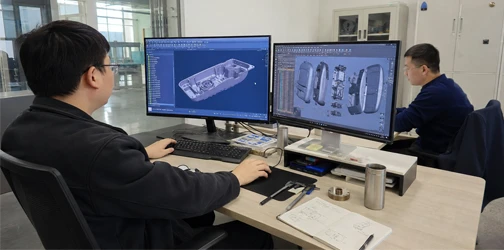
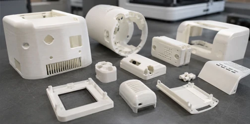
Maidder provides injection molding DFM services to evaluate plastic part geometry, moldability, tooling requirements, tolerances, materials, assembly, and potential manufacturing risks before injection mold design and manufacturing.
Injection Molding DFM Analysis for Plastic Parts
A part that works in CAD or as a prototype may still create problems when converted into an injection mold. Injection molding DFM evaluates both the plastic part and the tooling implications of the design so potential issues can be addressed while changes are still relatively easy to make.
Our engineers review wall thickness, draft angles, ribs, bosses, undercuts, parting lines, gates, ejection, cosmetic surfaces, and other critical features that can affect mold complexity and molded part quality. The resulting DFM feedback helps optimize the product before tooling investment and provides a clearer foundation for mold design, mold flow analysis, T1 sampling, and stable injection molding production.
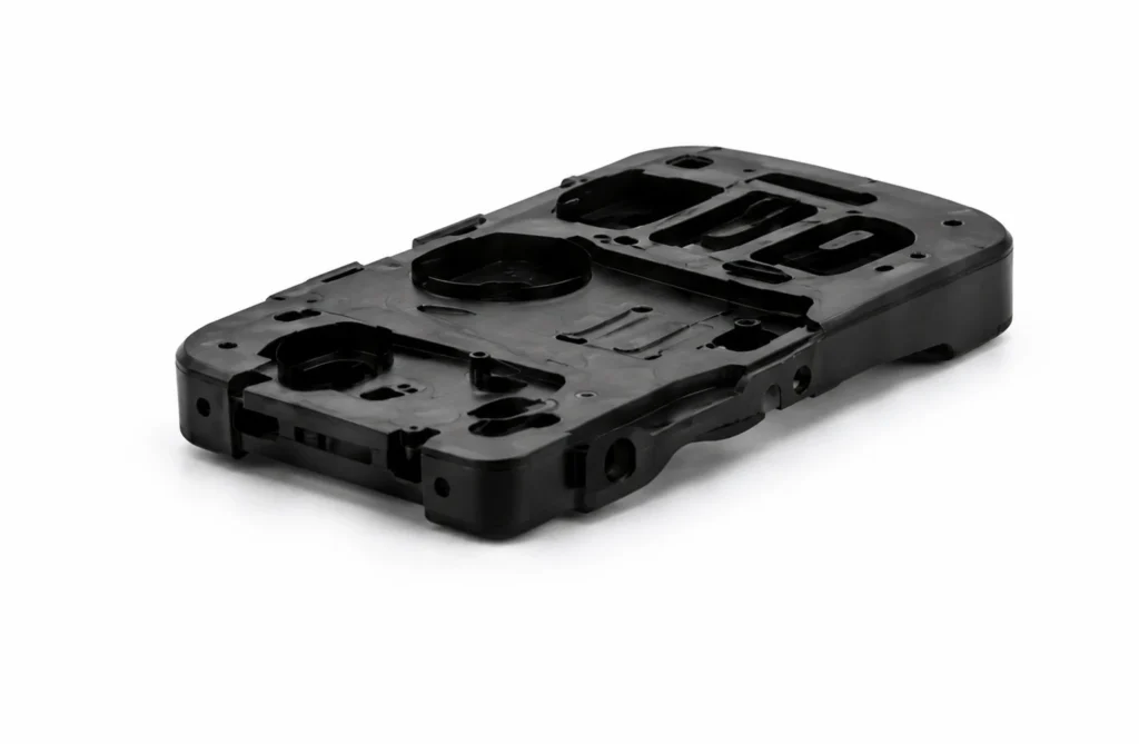
Wall Thickness & Transitions
Wall thickness affects material flow, cooling, shrinkage, sink marks, warpage, cycle time, and overall part consistency.
Our DFM review evaluates:
- Thick and thin sections
- Wall thickness consistency
- Sudden thickness transitions
- Cored sections
- Ribs and bosses
- Localized material buildup
Where appropriate, geometry changes can be recommended to improve moldability while maintaining required strength and function.
Draft Angles & Part Ejection
Draft allows molded parts to release from the core and cavity without excessive friction or damage.
Insufficient draft can contribute to drag marks, difficult ejection, cosmetic defects, or increased ejection force.
Our engineers review draft according to:
- Part depth
- Surface finish
- Texture
- Core and cavity orientation
- Ejection direction
- Product geometry
Draft requirements are considered before the mold structure is finalized.
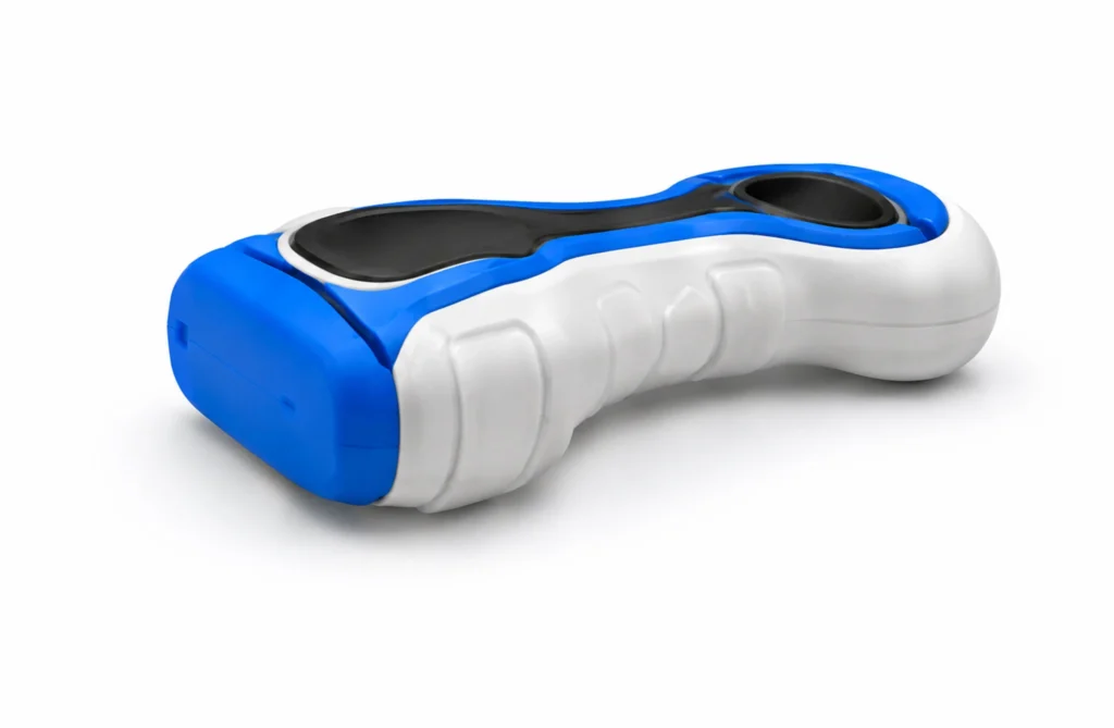
Undercuts & Side Actions
Undercuts can prevent a part from being released using a simple straight-pull mold.
Depending on the geometry, they may require:
- Slides
- Lifters
- Inserts
- Shut-offs
- Other tooling mechanisms
These features increase mold complexity and may affect tooling cost, maintenance, and cycle time.
DFM helps determine whether the undercut is necessary or whether the part geometry can be simplified.
Ribs, Bosses & Functional Features
Ribs, bosses, snap-fits, screw features, mounting points, and other structural details must balance product performance with molding requirements.
We review their dimensions, location, wall relationships, draft, and surrounding geometry to reduce risks such as sink marks, difficult filling, or tooling complexity.
Tooling-Focused DFM Review
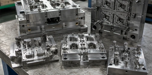
Injection mold DFM goes beyond basic part geometry. The design must also be evaluated according to how the mold will open, fill, cool, eject, and repeatedly produce the required plastic part.
Parting Line & Mold Direction
Parting line location affects mold structure, appearance, flash risk, dimensions, and undercut strategy.
During DFM, we evaluate:
- Mold opening direction
- Core and cavity orientation
- Visible surfaces
- Parting line locations
- Shut-off conditions
- Potential side actions
An appropriate mold direction can often simplify tooling and reduce unnecessary complexity.
Gate & Material Flow Considerations
Gate location affects how molten plastic enters the cavity and can influence filling, weld lines, pressure, appearance, and gate marks.
DFM considers potential gate locations according to part geometry, material, cosmetic requirements, and tooling strategy.
For more complex products, mold flow analysis can be used later to evaluate filling behavior in greater detail.
Ejection Considerations
The finished part must be removed consistently without deformation or unacceptable surface marks.
Our engineers review potential ejector locations together with part geometry, draft, ribs, bosses, cosmetic areas, and core retention.
Tolerances & Critical Dimensions
Not every dimension requires the same tolerance.
Overly tight tolerances may increase tooling precision, process control, mold adjustments, and inspection requirements.
DFM identifies critical dimensions and evaluates whether specified tolerances are practical for the material, geometry, mold structure, and product function.
Cosmetic & Surface Requirements
Surface texture, polish, visible parting lines, gates, ejector marks, and other tooling features can affect the final appearance of molded parts.
Cosmetic requirements should therefore be identified before mold design rather than after tooling is completed.
Our Injection Molding DFM Process
Maidder performs DFM before detailed mold engineering so product and tooling risks can be addressed before manufacturing begins.
01
CAD & Requirements Review
Provide your:
- 3D CAD files
- 2D drawings
- Plastic material
- Expected production quantities
- Surface finish
- Color requirements
- Critical tolerances
- Assembly requirements
- Cosmetic requirements
Our engineers review both product function and manufacturing requirements.
02
Moldability Analysis
The plastic part is evaluated for:
- Wall thickness
- Draft
- Ribs and bosses
- Undercuts
- Mold direction
- Parting lines
- Gates
- Ejection
- Materials
- Tolerances
- Cosmetic surfaces
- Assembly interfaces
Potential tooling and molding risks are identified before the design is released.
03
DFM Report & Engineering Feedback
The findings are organized into a DFM report so the product team can clearly review manufacturing concerns.
Depending on the project, the DFM report may include:
- Mold direction
- Core and cavity definition
- Parting line proposal
- Gate recommendations
- Ejector considerations
- Draft analysis
- Undercut analysis
- Wall thickness review
- Critical tolerance review
- Cosmetic surface definition
- Tooling risk recommendations
04
Design Revision & Confirmation
Recommended changes can be incorporated into the product CAD.
The revised design is reviewed again where necessary to confirm that critical DFM issues have been addressed.
05
Mold Design Handoff
Once the part design and DFM requirements are confirmed, the project can move into detailed mold design, mold flow analysis, and tooling manufacturing.
Review Your Plastic Part Before Cutting the Mold
Changes made before mold manufacturing are generally easier and less costly than modifications made after tooling has already been machined.
Our tooling engineers can review your design for moldability and identify potential part and tooling risks before the mold is released for manufacturing.
From DFM Review to Production-Ready Tooling
DFM is the engineering bridge between a finished plastic part design and the injection mold used to manufacture it. The goal is not only to identify design problems, but to translate an approved product into clear tooling requirements.
DFM to Mold Design
After DFM approval, confirmed information can be carried into mold design, including:
- Mold direction
- Parting strategy
- Core and cavity arrangement
- Gates and runners
- Ejection
- Slides and lifters
- Critical dimensions
- Cosmetic surfaces
- Material requirements
This gives the mold design team a clearer engineering foundation.
DFM & Mold Flow Analysis
For parts with more complex flow, dimensional, cosmetic, or warpage requirements, mold flow analysis can supplement the DFM review.
DFM evaluates overall manufacturability, while mold flow simulation provides deeper analysis of material filling, pressure, weld lines, air traps, cooling, and predicted warpage.
DFM to Mold Manufacturing
Once the plastic part and tooling strategy are approved, the mold can move into manufacturing with fewer unresolved design questions.
This helps reduce late tooling changes and improves communication between product engineers, mold designers, mold makers, and injection molding teams.
DFM to T1 Validation
DFM recommendations ultimately need to be confirmed through physical molded parts.
T1 samples can be evaluated for:
- Dimensions
- Fit and assembly
- Surface appearance
- Parting lines
- Gate marks
- Ejection
- Sink and warpage
- Functional requirements
Feedback from T1 can then be used for final mold optimization and production approval.
A typical Maidder workflow includes:
CAD Review → Injection Molding DFM → Design Revision → Design Approval → Mold Design → Mold Flow Analysis → Mold Manufacturing → T1 Sampling → Tool Validation → Production Injection Molding
Injection Molding DFM FAQs

What is DFM for injection molding?
DFM for injection molding is the process of reviewing a plastic part before mold manufacturing to determine whether it can be molded reliably and efficiently.
The review may include wall thickness, draft, ribs, bosses, undercuts, parting lines, gates, ejection, tolerances, materials, cosmetic requirements, and tooling complexity.
The objective is to identify potential design and moldability problems before significant tooling investment is made.
What is included in an injection molding DFM report?
A DFM report can include analysis and recommendations related to:
- Mold direction
- Wall thickness
- Draft angles
- Undercuts
- Core and cavity
- Parting lines
- Gates
- Ejector locations
- Critical tolerances
- Materials
- Cosmetic surfaces
- Tooling risks
The exact report content depends on the part design and project requirements.
When should injection molding DFM be performed?
DFM should ideally be completed before detailed mold design and before steel cutting begins.
It is commonly performed after the plastic part design is sufficiently developed but while CAD modifications are still practical.
DFM can also be used to review an existing design that is being transferred to a new injection mold or manufacturing supplier.
What is the difference between DFM and mold flow analysis for injection molding?
DFM focuses on part geometry feasibility, mold structure, manufacturability risks and design modifications to make the part moldable. Mold flow simulation is a supplementary CAE tool to predict filling, cooling, warpage, air traps and weld lines after the basic design passes DFM check. DFM comes first; mold flow is usually recommended for complex parts, thin walls, multi-cavity tools or high-volume production to further optimize process parameters.
What risks will occur if we skip injection molding DFM review?
Skipping DFM often leads to costly mold rework and project delays. Common issues include sink marks, warpage, short shots, poor ejection, visible cosmetic defects and unrealistic tolerances. Fixing geometry issues at CAD stage is low-cost, while modifying hardened steel after mold fabrication requires high expenses and multiple weeks of lead time. DFM reduces tooling revision risk and stabilizes mass production yield.
Contact Us
Have a product idea or manufacturing requirement? Our engineering team supports you from product development and rapid prototyping to custom injection molds, injection molding and mass production. Share your CAD files, drawings or project details, and we’ll help define the right solution.