
Injection Mold Design Services for Production Tooling
Design reliable injection molds for consistent part quality, efficient molding cycles, and long-term production.
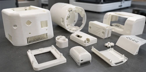
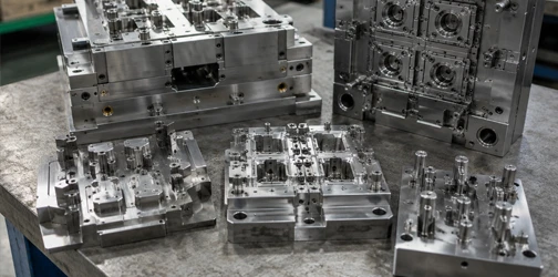
Maidder provides injection mold design services for plastic parts ranging from simple single-cavity tools to complex multi-cavity molds with slides, lifters, inserts, hot runners, and other specialized structures.
Production-Focused Injection Mold Design
A successful injection mold must do more than reproduce the shape of a plastic part. Mold structure affects material flow, cooling, ejection, dimensional consistency, surface appearance, cycle time, maintenance, and long-term production stability.
Our mold design engineers evaluate these requirements together when developing the tooling concept. By connecting mold design with DFM, mold flow analysis, mold manufacturing, T1 validation, and injection molding, we help prepare tooling for stable production before steel cutting begins.
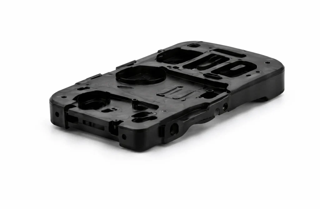
Cavity & Core Design
The cavity and core define the final molded geometry and are central to the overall mold structure.
Our engineers consider:
- Part orientation
- Core and cavity side
- Shrinkage allowance
- Critical dimensions
- Cosmetic surfaces
- Shut-off areas
- Steel conditions
- Inserts
- Machining access
The design is developed around both molded part requirements and practical mold manufacturing.
Parting Line & Mold Structure
Parting line selection can affect appearance, flash, dimensional accuracy, tooling complexity, and part release.
We evaluate the product geometry to define an appropriate parting strategy while minimizing unnecessary side actions where possible.
For complex geometries, the mold may incorporate slides, lifters, collapsible features, inserts, or other mechanisms.
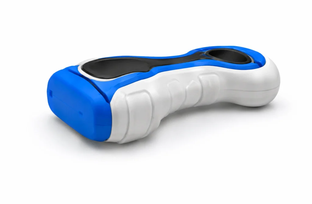
Runner & Gate Design
The runner and gate system controls how molten plastic enters and fills the mold cavity.
Gate type, location, size, and runner configuration are selected according to:
- Part geometry
- Plastic material
- Flow length
- Cosmetic requirements
- Weld line considerations
- Production volume
- Cavity layout
- Degating requirements
Both cold runner and hot runner solutions can be considered depending on project requirements.
Ejection System Design
The molded part must release from the tool consistently without deformation or unacceptable ejector marks.
Ejection design may include ejector pins, sleeves, stripper systems, or other mechanisms based on part geometry and mold structure.
Ejection force, location, product stiffness, draft, cosmetic surfaces, and tooling interference are reviewed during mold design.
Cooling, Cavitation and Mold Efficiency
Production mold design must balance part quality with cycle efficiency and long-term reliability. Cooling, cavity layout, machine compatibility, and tooling components all influence how consistently the mold performs in repeat production.
Mold Cooling Design
Cooling channels help control mold temperature and solidification of the molded part.
Our mold engineers consider cooling around cavity and core areas, thick sections, inserts, and other regions where uneven temperature may affect cycle time, shrinkage, or warpage.
Cooling design is coordinated with gates, ejectors, slides, and other mold components to avoid structural conflicts.
Single-Cavity & Multi-Cavity Mold Design
Cavity quantity is selected according to expected production volume, part size, mold dimensions, machine capacity, cycle requirements, and tooling investment.
Single-cavity molds may be appropriate for larger or lower-volume parts.
Multi-cavity molds can increase output per cycle for higher-volume manufacturing but require balanced filling, cooling, and ejection across all cavities.
Hot Runner & Cold Runner Design
Cold runner systems provide a conventional tooling approach and can be suitable for many production requirements.
Hot runner systems can reduce runner waste and support higher production efficiency where the material, product design, and manufacturing volume justify the additional tooling complexity.
The runner strategy is selected according to material, cavities, quality requirements, production volume, and total manufacturing cost.
Standardized Mold Components
Where appropriate, standardized mold bases, ejector components, guide elements, cooling fittings, and other tooling components can simplify mold manufacturing, maintenance, and future replacement.
Component standards can also be coordinated with customer requirements or the intended production location.
Our Injection Mold Design Process
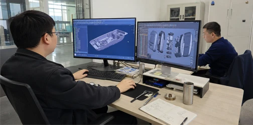
Maidder develops mold designs through a structured engineering process before mold manufacturing begins.
01
CAD & Tooling Requirements Review
We review the product CAD, drawings, material, expected quantities, tolerances, surface requirements, molding machine conditions, and tool life requirements. The tooling strategy is defined based on both part and production requirements.
02
DFM & Mold Concept
DFM findings are used to confirm key mold design inputs such as:
- Parting line
- Draft
- Undercuts
- Gate requirements
- Ejection
- Cosmetic areas
- Critical dimensions
- Mold direction
A preliminary tooling concept is then established.
03
3D Mold Structure Design
The complete mold structure is developed in 3D. This may include:
- Core and cavity
- Mold base
- Cavity layout
- Runners and gates
- Cooling circuits
- Ejector system
- Slides and lifters
- Inserts
- Hot runner components
- Alignment and guiding systems
04
Engineering Review & Optimization
The mold design is checked for component interference, machining feasibility, assembly, maintenance access, cooling, ejection, and molding operation. Where appropriate, mold flow analysis can also support gate, filling, cooling, and warpage decisions.
05
Design Approval & Manufacturing Release
After critical tooling details are confirmed, the mold design is released for mold manufacturing. Approved 3D tooling data and supporting drawings provide the manufacturing team with the information required for CNC machining, EDM, grinding, fitting, assembly, and mold trials.
Need a Production-Ready Injection Mold Design?
Maidder can review your CAD files, plastic material, expected production volume, machine requirements, tolerances, and surface specifications before mold manufacturing begins.
Our mold design, mold making, and injection molding teams work together to develop tooling around both part quality and real production requirements.
From Mold Design to Tool Manufacturing and Validation
Injection mold design should be developed around how the tool will actually be manufactured, assembled, tested, maintained, and used in production.Maidder connects mold engineering directly with mold making and injection molding.
Design for Mold Manufacturing
Tooling geometry is reviewed for machining, EDM, grinding, polishing, fitting, and assembly requirements before manufacturing.
This helps reduce unnecessary complexity and makes critical mold components more practical to manufacture and maintain.
Design for T1 Validation
The mold is designed with the first molding trial in mind.
Gate locations, vents, cooling, ejection, shut-offs, and adjustable tooling details can influence how efficiently issues identified during T1 sampling can be corrected.
Design for Mold Maintenance
Wear components, slides, lifters, inserts, ejectors, and other moving or replaceable parts should be accessible for maintenance throughout the mold’s production life.
Where appropriate, replaceable inserts or standardized components can simplify service and repair.
From Mold Design to Production
A typical Maidder tooling workflow includes: DFM → Mold Design → Mold Flow Analysis → Design Approval → Mold Manufacturing → Mold Assembly → T1 Sampling → Mold Optimization → Tool Validation → Production Injection Molding
Connecting these stages helps ensure that engineering decisions made during mold design continue through tooling manufacture and production validation.
Injection Mold Design FAQs
What is injection mold design?
Injection mold design is the engineering process of developing the tooling structure used to manufacture plastic parts through injection molding.
It typically includes cavity and core design, parting lines, cavity layout, gates and runners, cooling channels, ejection systems, slides, lifters, inserts, mold bases, and other tooling components.
The design must consider both the plastic part requirements and the conditions required for reliable production.
What information is needed to design an injection mold?
A 3D CAD model is normally the primary input.
Other useful information includes:
- Plastic material
- 2D drawings
- Critical tolerances
- Surface finish
- Expected annual and lifetime production volume
- Mold life requirements
- Molding machine specifications
- Preferred runner system
- Customer tooling standards
- Assembly requirements
These inputs help determine the appropriate mold structure.
How do you choose the parting line and gate location?
Parting line selection depends on part geometry, appearance, dimensional requirements, ejection, undercuts, and mold construction.
Gate location depends on material flow, geometry, wall thickness, cosmetic requirements, weld lines, pressure, and how the gate will be removed.
Both should be evaluated before mold manufacturing because they directly influence tooling structure and molded part quality.
What is the difference between mold design and mold flow analysis?
Mold design develops the physical tooling structure, including the cavity, core, runners, gates, cooling, ejection, slides, lifters, and mold components.
Mold flow analysis uses simulation to predict how plastic fills, packs, cools, and may warp within the mold.
Mold flow analysis can support mold design decisions, but the two are separate engineering activities.
What is the difference between mold design and DFM?
DFM evaluates whether the plastic part itself is suitable for injection molding and identifies design changes that can improve manufacturability.
Mold design uses the approved product geometry and manufacturing requirements to develop the actual tooling structure.
DFM therefore typically comes before detailed mold design.
Can Maidder continue from mold design to mold making and injection molding?
Yes. Maidder can continue from DFM and mold design through mold flow analysis, precision mold manufacturing, assembly, T1 sampling, tooling optimization, injection molding, secondary operations, assembly, and mass production.
This creates a continuous workflow from tooling engineering to stable production.
Contact Us
Have a product idea or manufacturing requirement? Our engineering team supports you from product development and rapid prototyping to custom injection molds, injection molding and mass production. Share your CAD files, drawings or project details, and we’ll help define the right solution.