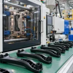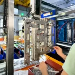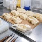
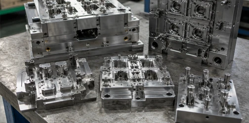

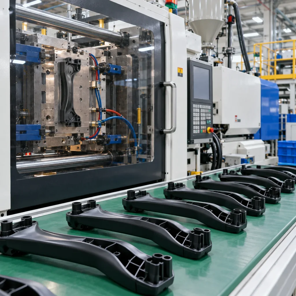
A practical guide to dfm, mold design, mold flow analysis, precision tooling and t1 validation. This guide explains the key engineering decisions required to turn an approved plastic part into production-ready injection tooling.
Engineering for Reliable Production
A Practical Guide to DFM, Mold Design, Mold Flow Analysis, Precision Tooling and T1 Validation
Executive Summary
An injection mold is not simply a tool used to shape plastic. Its design determines part quality, dimensional consistency, cycle time, production efficiency and long-term manufacturing stability.
Reliable mold manufacturing therefore begins before machining—with DFM, mold concept development, material selection, mold flow analysis and a clear understanding of production requirements.
This guide explains the key engineering decisions required to turn an approved plastic part into production-ready injection tooling.
01. Start With Production Requirements
Before mold design begins, define:
- Plastic material
- Part dimensions
- Critical tolerances
- Surface requirements
- Expected annual volume
- Required mold life
- Number of cavities
- Production location
- Injection machine requirements
- Automation requirements
- Quality documentation
These requirements determine the appropriate tooling strategy
02. DFM Before Mold Design
The mold should not be designed around unresolved product problems.
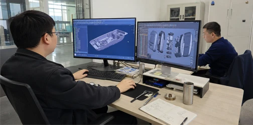
A tooling DFM review should identify risks before mold manufacturing begins.
Key DFM Checks
Wall Thickness Analysis
Identify potential sink, shrinkage and cooling issues.
Draft Angle Evaluation
Confirm reliable part release.
Undercut Review
Determine whether slides, lifters or other mechanisms are required.
Parting Line Analysis
Optimize mold separation while considering appearance and flash risk.
Gate Location & Type
Evaluate filling behavior and gate appearance.
Ejection Strategy
Determine suitable ejector locations and forces.
Tolerance Review
Evaluate whether dimensional requirements are achievable and repeatable.
Assembly Review
Check interfaces and tolerance relationships between molded components.
03. Understand Injection Mold Structure
A typical production mold contains multiple systems working together.
Core & Cavity
Create the primary geometry of the molded component.
Mold Base
Provides the structural platform for mold components.
Inserts
Allow localized geometry, easier replacement or use of different tool steels.
Slides & Lifters
Create features that cannot be released through the normal mold-opening direction.
Runner System
Transfers molten plastic from the machine nozzle to the cavity.
Gates
Control where plastic enters the part.
Cooling Channels
Control mold temperature and remove heat from the molded part.
Ejection System
Removes the cooled component from the mold.
A mold should be engineered as a complete production system rather than a collection of individual components.
04. Gate & Runner Design
Gate strategy influences:
- Filling pattern
- Pressure
- Weld lines
- Air traps
- Gate vestige
- Packing
- Appearance
Common solutions include:
Edge Gate
Simple and widely used for many molded products.
Pin Gate
Provides a relatively small gate mark and automatic separation in appropriate mold structures.
Submarine Gate
Can enable automatic degating.
Direct Gate
Provides efficient filling but leaves a larger gate vestige.
Hot Runner
Reduces runner waste and can support high-volume or multi-cavity production.
There is no universally “best” gate. Selection depends on product geometry, material, appearance and production requirements.
05. Design an Effective Cooling System
Cooling frequently represents a significant portion of the molding cycle.
Poor cooling can lead to:
- Long cycle times
- Uneven shrinkage
- Warpage
- Dimensional variation
- Production instability
Cooling channels should provide balanced heat removal across the part.
Engineering Objective
Not simply:
Cool the mold faster.
But:
Cool the molded part uniformly and repeatably.
06. Use Mold Flow Analysis to Reduce Risk
Mold flow simulation can help engineers predict material behavior before tooling is finalized.
Filling Analysis
Evaluates how molten plastic fills the cavity.
Pressure Analysis
Identifies high-pressure regions and filling difficulty.
Weld Line Prediction
Shows where separate flow fronts may meet.
Air Trap Prediction
Identifies areas where trapped air may affect filling or appearance.
Cooling Analysis
Evaluates temperature distribution.
Warpage Analysis
Predicts deformation caused by shrinkage, material orientation and uneven cooling.
Example Engineering Decision
Analysis: Weld line occurs near a high-load feature.
Potential Action: Reconsider gate location or flow direction.
Goal: Move the weld line away from the critical area before mold manufacturing.
07. Select Mold Steel Based on Production Needs
Mold steel selection should reflect production volume, plastic material, surface requirements and expected tool life.
| Mold Steel | Typical Characteristics | Common Use |
| P20 | Pre-hardened, machinable | General production molds |
| 718H | Good hardness and polishability | Medium/high production tooling |
| NAK80 | Good polishability and dimensional stability | Cosmetic mold applications |
| S136 | Corrosion resistance and polishability | Clear/corrosive-material applications |
| H13 | High hardness and wear resistance | Inserts and demanding tooling applications |
Final selection should be based on the specific application rather than steel grade alone.
08. Precision Mold Manufacturing
After mold design approval, tooling enters precision manufacturing.
CNC Machining
Produces mold bases, cavities, cores and structural components.
EDM
Creates deep ribs, sharp internal details and geometries difficult to machine conventionally.
Wire EDM
Used for precision profiles, inserts and other detailed features.
Grinding
Supports high-accuracy dimensions and fitting surfaces.
Polishing / Texture Preparation
Creates the specified mold surface for cosmetic parts.
Fitting & Assembly
Ensures cores, cavities, slides, lifters and ejector systems operate correctly as a complete tool.
09. Inspect Before Mold Trial
Before T1, critical tooling dimensions and mold functions should be verified.
Inspection can include:
- Core and cavity dimensions
- Insert dimensions
- Shut-off surfaces
- Slide movement
- Ejection system
- Cooling circuit
- Mold assembly
- Mold opening and closing
- Surface finish
10. T1 Mold Trial
T1 is the first opportunity to evaluate the complete relationship between:
Product Design + Material + Mold + Injection Process
T1 samples should be evaluated for:
- Complete filling
- Flash
- Short shots
- Sink marks
- Weld lines
- Warpage
- Gate appearance
- Ejector marks
- Dimensions
- Surface quality
- Assembly
- Function
11. From T1 to Mold Approval
Not every T1 issue requires mold modification.
Problems should first be classified.
Process-Related
Potentially improved through:
- Temperature
- Pressure
- Injection speed
- Packing
- Cooling
- Cycle settings
Tool-Related
May require:
- Gate modification
- Venting changes
- Steel adjustment
- Cooling changes
- Ejection modification
Design-Related
May require product geometry changes.
The engineering team should determine the root cause before modifying tooling.
12. What Drives Injection Mold Cost?
Major mold cost drivers include:
- Part size
- Product complexity
- Number of cavities
- Slides and lifters
- Mold steel
- Hot runner system
- Tight tolerances
- Surface texture / polish
- Tool life requirement
- Mold standard
- Inspection requirements
The lowest initial mold price does not necessarily create the lowest manufacturing cost over the product lifecycle.
13. Injection Mold Supplier Evaluation Checklist
Before selecting a tooling partner, evaluate:
☐ DFM capability
☐ Mold design capability
☐ Mold flow analysis
☐ CNC / EDM capability
☐ Precision inspection
☐ Mold assembly capability
☐ In-house mold trial capability
☐ T1 reporting
☐ Engineering change management
☐ Quality documentation
☐ Injection molding capability
☐ Production transfer support
A supplier capable of both mold manufacturing and injection molding can evaluate tooling decisions against actual production requirements.
14. Injection Mold RFQ Checklist
For a more accurate tooling evaluation, provide:
- 3D CAD file
- 2D drawings where available
- Plastic material
- Color
- Surface texture
- Annual production volume
- Expected mold life
- Critical tolerances
- Cosmetic requirements
- Preferred cavity count
- Hot/cold runner preference if specified
- Production location
- Inspection requirements
Final Takeaway
Build the Mold Around Production
Reliable injection tooling requires more than precision machining.
DFM, mold flow, mold structure, steel selection, cooling, machining, inspection and mold trials should all work toward one objective:
Stable, repeatable injection molding production.
Have a Mold Project?
Send your CAD files and production requirements for tooling evaluation and DFM feedback.